20 Haziran 2015 Cumartesi

DHT11 Working Code Arduino

#include "DHT.h"
 
#define DHTPIN 2    // pin do którego podłączyliśmy dane z czujnika
 
#define DHTTYPE DHT11   // typ czujnika
 
DHT dht(DHTPIN, DHTTYPE);
 
void setup() {
  Serial.begin(9600); // inicjujemy połączenie szeregowe
  Serial.println("DHTxx test!");
  dht.begin(); // włączamy czujnik
}
 
void loop() {
 
  float h = dht.readHumidity(); // odczyt wilgotności
  float t = dht.readTemperature(); // odczyt temperatury
 
  if (isnan(t) || isnan(h)) {
    Serial.println("Failed to read from DHT");
  } else {
    Serial.println(t); // Wyświetlenie linijki z temperaturą
    Serial.println(h); // Wyświetlenie linijki z wilgotnością
  }
}

14 Haziran 2015 Pazar

pir sensor

    int pirPin = 22;
    
    int minSecsBetweenEmails = 60; // 1 min
    
    long lastSend = -minSecsBetweenEmails * 1000l;
    
    void setup()
    {
      pinMode(pirPin, INPUT);
      Serial.begin(9600);
    }
    
    void loop()
    {
      long now = millis();
      if (digitalRead(pirPin) == HIGH)
      {
        if (now > (lastSend + minSecsBetweenEmails * 1000l))
        {
          Serial.println("MOVEMENT");
          lastSend = now;
        }
        else
        {
          Serial.println("Too soon");
        }
      }
      delay(500);
    }

********************************************

// Uses a PIR sensor to detect movement, buzzes a buzzer
// more info here: http://blog.makezine.com/projects/pir-sensor-arduino-alarm/
// email me, John Park, at jp@jpixl.net
// based upon:
// PIR sensor tester by Limor Fried of Adafruit
// tone code by michael@thegrebs.com

 
int ledPin = 13;                // choose the pin for the LED
int inputPin = 2;               // choose the input pin (for PIR sensor)
int pirState = LOW;             // we start, assuming no motion detected
int val = 0;                    // variable for reading the pin status
int pinSpeaker = 10;           //Set up a speaker on a PWM pin (digital 9, 10, or 11)

void setup() {
  pinMode(ledPin, OUTPUT);      // declare LED as output
  pinMode(inputPin, INPUT);     // declare sensor as input
  pinMode(pinSpeaker, OUTPUT);
  Serial.begin(9600);
}

void loop(){
  val = digitalRead(inputPin);  // read input value
  if (val == HIGH) {            // check if the input is HIGH
    digitalWrite(ledPin, HIGH);  // turn LED ON
    playTone(300, 160);
    delay(150);

    
    if (pirState == LOW) {
      // we have just turned on
      Serial.println("Motion detected!");
      // We only want to print on the output change, not state
      pirState = HIGH;
    }
  } else {
      digitalWrite(ledPin, LOW); // turn LED OFF
      playTone(0, 0);
      delay(300);    
      if (pirState == HIGH){
      // we have just turned off
      Serial.println("Motion ended!");
      // We only want to print on the output change, not state
      pirState = LOW;
    }
  }
}
// duration in mSecs, frequency in hertz
void playTone(long duration, int freq) {
    duration *= 1000;
    int period = (1.0 / freq) * 1000000;
    long elapsed_time = 0;
    while (elapsed_time < duration) {
        digitalWrite(pinSpeaker,HIGH);
        delayMicroseconds(period / 2);
        digitalWrite(pinSpeaker, LOW);
        delayMicroseconds(period / 2);
        elapsed_time += (period);
    }
} 
 
********************************************* 

documents

http://georgehk.blogspot.com.tr/
https://learn.adafruit.com/series/learn-arduino

LED Blinking in Arduino UNO R3

LED Blinking in Arduino UNO R3

1. What is Arduino?

Arduino is an open-source electronics prototyping platform based on flexible, easy-to-use hardware and software. It's intended for artists, designers, hobbyists and anyone interested in creating interactive objects or environments.

2. What Arduino can do

Arduino can sense the environment by receiving input from a variety of sensors and can affect its surroundings by controlling lights, motors, and other actuators. The microcontroller on the board is programmed using the Arduino programming language (based on Wiring) and the Arduino development environment (based on Processing). Arduino projects can be stand-alone or they can communicate with software running on a computer (e.g. Flash, Processing, MaxMSP).

3. Arduino Boards

Browse the wide range of official Arduino boards
Arduino Boards Arduino Boards

4. Getting Starting with Arduino

Get the latest version from the download page.
When the download finishes, unzip the downloaded file. Make sure to preserve the folder structure. Double-click the folder to open it. There should be a few files and sub-folders inside.
Connect the Arduino board to your computer using the USB cable. The green power LED (labelled PWR) should go on.

5. Installing drivers for Arduino Uno

It is important to follow the steps mentioned next to be able to use the Arduino Uno and some other boards. Please check the Arduino website for up-to-date references.
  1. Plug your board in and wait for Windows to begin the driver installation process. 
  2. Click on the Start menu, and open Control Panel. 
  3. In Control Panel, navigate to System and Security. Next, click on System. Once the System window is up, open Device Manager. 
  4. Look under Ports (COM & LPT). Check the open port named Arduino UNO. 
  5. Right-click on the Arduino UNO port and choose the Update Driver Software option. 
  6. Next, choose the Browse my computer for driver software option. 
  7. Finally, navigate and select the Uno's driver file, named ArduinoUNO.inf, located in the Drivers folder of the Arduino software download. 
  8. Windows will finish the driver installation from there and everything will be fine. 
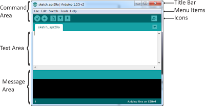
To open arduino UNO, just go to the folder download and double click on arduino and it will display a window depicted in next figure.
Arduino UNO r3

6. Creating Your First Sketch in the IDE

An Arduino sketch is a set of instructions that you create to accomplish a particular task you want to achieve; in other words, a sketch is a program.
For the very first project, we are going to create the LED blink sketch. We will also learn exactly how the hardware and the software for this project works as we go, learning a bit about electronics and coding in the Arduino language (which is a variant of C).
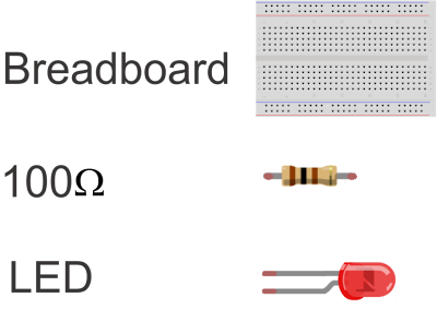
Parts Required:
LED Blinking Arduino
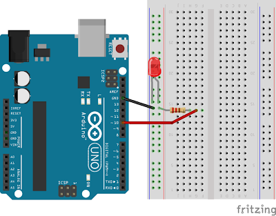
Let's see the sketch for this project, just connect the anode to GND and the Cathode to pin 10 of Arduino's board using 100ohm resistor.
Sketch Arduino led blinking
In the text area type the code:
 
// LED blink Flasher
int ledPin = 10;
void setup() {
   pinMode(ledPin, OUTPUT);
}
void loop() {
   digitalWrite(ledPin, HIGH);
   delay(1000);
   digitalWrite(ledPin, LOW);
   delay(1000);
}

First press verify icon to check if there are some errors, after press upload icon to run your program, if you have done all correctly, you should see the LED blinking every second.

Turn ON/OFF LED in Arduino Using Visual Studio

1. Problem Statement

In this tutorial we will learn how to Turn ON and Turn OFF a LED in arduino, but this time using Visual Studio using the serial Port and C# programming language.

2. What is a serial interface?

A serial interface is used for information exchange between computers and peripheral devices. When using a serial communication, the information is sent bit by bit (serial) over a cable. Modern serial interfaces are Ethernet, Firewire, USB, RS-485, etc. For our project we will use the USB port.
Visual Studio provide a serialPort control which we will use for this project.

3. Sketch for this project

We are going to use the sketch used in our first tutorial, which just need a LED, 100ohm resistors and wires to connect them with Arduino board, the next picture show the connections.
Turn ON OFF Led arduino Using C#

4. Source Code for Arduino

The source code for this project is simple to understand, but in this case we will get the information from the serial port dispatched by C# program and then we will verify to turn ON(1) or turn OFF(0), Type the following code in the text area of arduino the code is explained line by line.
 
#define BaudRate 9600
#define LEDPin    10
char incomingOption;

void setup()
{
  pinMode(LEDPin, OUTPUT);
  // serial communication
  Serial.begin(BaudRate);
}
void loop()
{
     //read from serial port getting information from VS 2013
     incomingOption = Serial.read();
     //verify incomingOption
     switch(incomingOption){
        case '1':
          // Turn ON LED
          digitalWrite(LEDPin, HIGH);
          break;
        case '0':
          // Turn OFF LED
          digitalWrite(LEDPin, LOW);
          break;
     }
}

5. Design the Interface in Visual Studio for communicate with Arduino

Design a interface with 3 buttons, the first one will turn ON the LED, the second one will turn OFF the LED and finally the third button will close the serial port.

Turn ON OFF LED arduino with C#

You need to drag and drop a serialPort control to the design area and set properties BaudRate to 9600 and PortName to COM4 and that's all for the design part.
Next we need to write the code for turning ON and Turning OFF.
 
public partial class frmTurnONTurnOFFLED : Form
{
   public frmTurnONTurnOFFLED()
   {
      InitializeComponent();
   }
   private void btnTurnON_Click(object sender, EventArgs e)
   {
      try
      {
         serialPort1.Write("1"); //send 1 to Arduino
      }
      catch (Exception ex)
      {
         MessageBox.Show(ex.Message);
      }
   }
   private void btnTurnOFF_Click(object sender, EventArgs e)
   {
      try
      {
         serialPort1.Write("0"); //send 0 to Arduino
      }
      catch (Exception ex)
      {
         MessageBox.Show(ex.Message);
      }
   }
   private void frmTurnONTurnOFFLED_Load(object sender, EventArgs e)
   {
      serialPort1.Open(); //open serialPort
   }
   private void btnClosePort_Click(object sender, EventArgs e)
   {
      serialPort1.Close(); //close serialPort
   }        
}


Temperature Sensor LM35 in Arduino with C#

Temperature Sensor LM35 in Arduino with C#

Temperature sensor LM35 in Arduino with CSharp

1. Problem Statement

In this tutorial we will learn how use temperature sensor LM35 to get temperature from the environment in Arduino and process the information in C# via the serial Port, Also we will show the temperature in Celsius and Fahrenheit degrees.

2. LM35 Precision Centigrade Temperature Sensors

The LM35 is integrated-circuit temperature sensor, whose output voltage is linearly proportional to the Celsius (Centigrade) temperature. The LM35 thus has an advantage over linear temperature sensors calibrated in ° Kelvin, as the user is not required to subtract a large constant voltage from its output to obtain convenient Centigrade scaling. The LM35 does not require any external calibration or trimming to provide typical accuracies of ±1⁄4°C at room temperature and ±3⁄4°C over a full −55 to +150°C temperature range. Low cost is assured by trimming and calibration at the wafer level.. The LM35 is rated to operate over a −55° to +150°C temperature range.
Previously we need to understand couple of things, so to connect it to Arduino, you must connect VCC to Arduino 5V, GND to Arduino GND, and the middle pin you must connect to an Analog Pin, in my case we will use A0(Analog pin). This projects doesn't need any resistor or capacitor between the Arduino and the Sensor, but you need to know that Arduino ADC has a precision of 10 bits. This means:
5V / 2^10 = 5V / 1024, so 0.0049 is our factor. To get the temperature in Celsius from LM35, we calculate like this: Temperature Celsius = (pinA0 * 0.0049)*100

3. Sketch for this project

For implement this project we will required the following materials:
  • LM35 temperature sensor 
  • Couple of Wires
  • Arduino UNO R3
The next picture show the sketch for this project

4. Source code to Get Temperature from LM35 in Arduino

Go to Arduino text Area and type de following code, first we define the analog Pin, sensorValue and temperature in Celsius, second we start to open communication for serial, third we get the voltage from LM35 and convert to celsius degree and write in the serial port and get the information from C# and show the temperature.
 
#define sensorPin 0 //A0 Pin
int sensorValue = 0; 
float celsius = 0;
void setup() { 
  Serial.begin(9600); //start Serial Port
} 
void loop() { 
  getTemperature();
  //send celsious value to Port and read from C#
  Serial.println(celsius); 
  delay(1000); 
}
void getTemperature(){
  //get sensorPin voltage
  sensorValue = analogRead(sensorPin);
  //convert voltage to celsius degree
  celsius = (sensorValue * 0.0049) *100; 
}

5. Design Project in C# to show temperature in Celsius and Fahrenheit

Design an interface like depicted in next figure, for design the thermometer I used the Old GDI+, also we will add a TextBox to show the temperature get from serial Port and finally one Button to show the temperature in the thermometer.


The next code is for button Show temperature, first we verify if the port is open and after get the temperature from serial port which was send by arduino and round this value and send that value to a function which is in charge to draw the current temperature in the thermometer.
 
private void btnShowTemperature_Click(object sender, EventArgs e)
{
  try
  {
     if (serialPort1.IsOpen)
     {
       //get Temperature from serial port sent by Arduino
        
       int temperature = (int)(Math.Round(Convert.ToDecimal(
                          serialPort1.ReadLine()), 0));
       txtTemperature.Text = temperature.ToString();
       //draw temperature in the thermometer
       DrawTemperatureLevel(temperature);
     }
   }
   catch (Exception ex)
   {
     MessageBox.Show(ex.Message);
   }          
}        

6. Running the project

First in arduino UNO R3 press the button Upload and then go to visual studio and run the project, second press the button Show Temperature and then it will show the temperature in the thermometer as shown next figure.


Temperature and Humidity Sensor DHT11 in Arduino with C#

Temperature and Humidity Sensor DHT11 in Arduino with C#

Temperature and Humidity Sensor DHT11 in Arduino with C#

1. Problem Statement

In this tutorial we will learn how use sensor to get temperature and humidity from the environment using DHT11 Sensor in Arduino and process the information in C# via the serial Port. We will show the temperature in Celsius and Humidity.

2. Temperature and Humidity Sensor DHT11

The DHT11 is a basic, ultra low cost digital temperature and humidity sensor. It uses a capacitive humidity sensor and a thermostat to measure the surrounding air, and spits out a digital signal on the data pin. It's fairly simple to use, but requires careful timing to grab data. The only real downside of this sensor is you can only get new data from it once every 2 seconds. In the market you will find many models, some of them have 3 or 4 pins, so be carefully and read the technical specifications. The technical specification of DHT11 are:
  • 3 to 5V power and I/O
  • 2.5mA max current use during conversion (while requesting data)
  • Good for 20-80% humidity readings with 5% accuracy
  • Good for 0-50°C temperature readings ±2°C accuracy
  • No more than 1 Hz sampling rate (once every second)
  • Body size 15.5mm x 12mm x 5.5mm
  • 3 pins with 0.1" spacing


3. Sketch for this project

For implement this project we will required the following materials:
  • DHT11 temperature and humidity sensor
  • Wires
  • Arduino UNO R3
The next picture show the sketch for this project

In the next figure we can see the first pin is connected to pin digital 2 in arduino board, the middle one to 5v and the last one is connected to GND.

4. Arduino Source Code to get Temperature and Humidity from DHT11

The source code in arduino is not so complicated, as we can see first you need to add the library dht11.h to start to use DHT11 temperature and humidity sensor and then define the digital pin you will use to read the information from the sensor and finally read the information from dht11 sensor (temperature and humidity) and print in the serial port for further reading from C#.
 
#include <dht11.h>
//Declare objects
dht11 DHT11;
//Pin Numbers
#define DHT11PIN 2
void setup() 
{
  Serial.begin(9600);
}
void loop() 
{
  int chk = DHT11.read(DHT11PIN);
  //read temperature in celsius degree and print in the serial port
  Serial.print((float)DHT11.humidity, 2);
  Serial.print(",");
  //read humidity and print in the serial port
  Serial.print((float)DHT11.temperature, 2);
  Serial.println();
  delay(2000);
}

5. Designing Project in C# to Show the Temperature and Humidity

To implement this project using C# we require to draw a gauge control and a needle, in my case I draw them using photoshop for displaying temperature and put the gauge picture in a PictureBox control and for movement of the needle we will make programmatically. Also we need a couple of TextBox to show the temperature, humidity and time. Every 10 seconds we will update the temperature and humidity so we need to use Timer controls and finally we will need a SerialPort control to read the information from the serial port. The design of the interface is shown in the next figure.

C# Source Code

As we can see this is the main part of the c# source code for this project, we split the information we get from arduino separate by commas into temperature and humidity and then draw that temperature in the gauge control.
 
private void timer1_Tick(object sender, EventArgs e)
{
    //read temperature and humidity every 10 seconds
    timer1.Interval = 10000;
    //read information from the serial port
    String dataFromArduino = serialPort1.ReadLine().ToString();
    //separete temperature and humidity and save in array
    String[] dataTempHumid = dataFromArduino.Split(',');
    //get temperature and humidity
    int Humidity = 
    (int)(Math.Round(Convert.ToDecimal(dataTempHumid[0]),0));
    int Temperature = 
    (int)(Math.Round(Convert.ToDecimal(dataTempHumid[1]),0));
    //draw temperature in the graphic
    drawTemperature(Temperature);
    txtHumidity.Text = Humidity.ToString()+" %";
    txtTemperatureCelsius.Text = Temperature.ToString()+" °C";
}
private void timer2_Tick(object sender, EventArgs e)
{
    txtTime.Text = DateTime.Now.ToLongTimeString();
}
private void frmTemperatureHumidity_Load(object sender, EventArgs e)
{
    needle = Image.FromFile("needle2.png");
     serialPort1.Open();
}

6. Running Project

Just press F5 to run the project and you will see the program start to read from the serial port and show in the gauge control, and every 10 seconds it will update with the new information getting from the DHT11 sensor.